Before you can measure anything, you need to know what you are looking at. Learning how to read construction drawings is the first real skill in estimating: a takeoff is only as accurate as your understanding of the plans, sections, schedules and notes behind it.
This guide walks through how to read construction plans the way an estimator does. You will learn the main sheet types, how sheet numbers work, where to find scale and revision information, how symbols and notes fit in, and how to follow one item across the whole drawing set before you measure it. We finish with a practical takeoff workflow in PDF takeoff software.
It is written for US contractors and estimators first, with a section on reading building plans in Australia at the end.
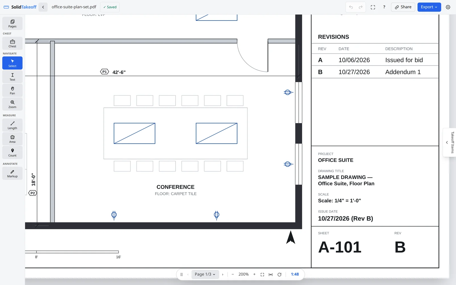
What Are Construction Drawings and Why Do They Matter for Takeoffs?
Construction drawings (often still called blueprints) are the set of sheets that describe what is to be built: where things go, how big they are, what they are made of and how they connect. A full set usually comes with written specifications that describe materials and workmanship in more detail.
For estimating, there is an important distinction:
- Reading the drawings means understanding the scope: which walls, finishes, fixtures and systems are included, and where the information about each one lives.
- Doing the takeoff means measuring the quantities of that scope: linear feet, square feet, counts and volumes.
If you skip the first step, the second one goes wrong. Many takeoff errors begin before measurement: an outdated revision, a missing detail, an incorrectly interpreted wall type or an unverified scale can all produce inaccurate quantities. Knowing how to read blueprints for estimating is what prevents those mistakes.
Understand the Different Types of Construction Drawings
A drawing set is organized by discipline and by view. These are the sheet types you will use most:
| Drawing type | What it shows | What an estimator takes from it |
|---|---|---|
| Floor plans | The building cut horizontally, seen from above | Wall runs, room areas, door and window locations, fixture counts |
| Elevations | Exterior or interior faces seen straight on | Heights, cladding and finish areas, window and door sizes |
| Sections | The building cut vertically | Wall and floor build-ups, ceiling heights, layers of construction |
| Details | Enlarged views of specific junctions | Trims, flashings, fixings, edge conditions, items that are easy to miss |
| Schedules | Tables of doors, windows, finishes, fixtures or equipment | Types, sizes, quantities, ratings and hardware |
| Reflected ceiling plans | The ceiling seen from below, as if in a mirror | Ceiling types and areas, light fittings, diffusers, bulkheads |
| MEP drawings | Mechanical, electrical and plumbing layouts | Duct and pipe runs, outlets, fixtures and equipment counts |
Site and civil drawings, structural drawings and landscape drawings follow the same idea for their own scope.
How to Read Construction Drawing Sheet Numbers
Sheet numbers tell you which discipline a sheet belongs to and what kind of view it holds. Many US drawing sets follow the sheet identification format in the US National CAD Standard, where a sheet number starts with a discipline designator:
- G: general (cover sheet, drawing index, code information)
- C: civil
- L: landscape
- S: structural
- A: architectural
- I: interiors
- M: mechanical
- E: electrical
- P: plumbing
- F: fire protection (some drawing sets use more specific or project-defined prefixes)
The first digit after the letter usually indicates the sheet type: 0 for general information, 1 for plans, 2 for elevations, 3 for sections, 4 for large-scale views, 5 for details and 6 for schedules and diagrams. So A-101 is typically the first architectural floor plan, A-301 an architectural section and A-601 an architectural schedule sheet.
Numbering conventions vary by firm and project, so always check the drawing index on the cover sheet rather than assuming.
Step 1: Check the Title Block, Drawing Index and Revisions
Every sheet has a title block, usually along the right-hand edge or bottom. Before you measure a single line, check:
- Project name and address, so you are on the right job.
- Sheet number and title, for example A-101, Ground Floor Plan.
- Issue status and date, such as "For Bid", "For Permit" or "For Construction".
- Revision number and date, and the revision history table.
- Scale, if the sheet has a single scale.
Then compare the sheets you have against the drawing index. A missing sheet is a missing scope. Look for revision clouds (the wavy outlines around changed areas) and the revision triangles (deltas) next to them. Revision clouds and delta symbols identify changes marked by the designer, but they may not capture every modification. Check the revision register, addenda and issued drawing set, and compare revisions where necessary. If you are working from two issues of the same set, our guide on how to compare construction drawing revisions covers that process.
Step 2: Understand Construction Symbols, Legends and Notes
Construction drawing symbols and abbreviations are a shorthand that lets a lot of information fit on one sheet. The legend (or symbols sheet, often in the G or A-000 series) explains the ones used in that set. The most common for takeoff are:
- Door tags and window marks: a number or code in a circle, hexagon or other shape that links each opening to the door or window schedule.
- Wall type tags: a code that links a wall to its build-up, often shown on a partition types sheet.
- Section and detail callouts: a circle split by a line, showing the detail or section number on top and the sheet it is drawn on underneath (for example 3 over A-501).
- Elevation markers: arrows that point at a wall and reference the elevation sheet that shows it.
- Grid lines: lettered and numbered lines that let you locate anything on any sheet.
- Room tags and finish codes: room name, number and sometimes the finish types that link to the finish schedule.
Common abbreviations include TYP (typical), SIM (similar), NIC (not in contract), EQ (equal), AFF (above finished floor), CLG (ceiling) and GWB (gypsum wallboard). Abbreviations are not fully standard, so check each set's abbreviation list.
Read the general notes too. A note like "all partitions to extend to underside of deck unless noted otherwise" can change a wall height, and therefore every drywall quantity in the job.
Step 3: Read Drawing Scales and Dimensions
US architectural drawings are usually drawn to imperial scales such as 1/8" = 1'-0" (1:96) for floor plans and 1/4" = 1'-0" (1:48) or larger for enlarged plans, while details are often at 1-1/2" = 1'-0" or 3" = 1'-0". Civil and site drawings often use engineering scales such as 1" = 20'.
When you read the scale:
- Check the scale on each view, not just the title block. One sheet can hold views at several scales.
- Use a graphic scale bar where provided. Unlike a written scale ratio, a graphic bar generally remains usable when a drawing is uniformly resized. However, scanning distortion or non-uniform stretching can make it unreliable, so verify against known written dimensions.
- Prefer written dimensions over scaling. If a dimension string says 24'-6", that number wins over anything you measure.
- Watch for NTS (not to scale) on diagrams and some details.
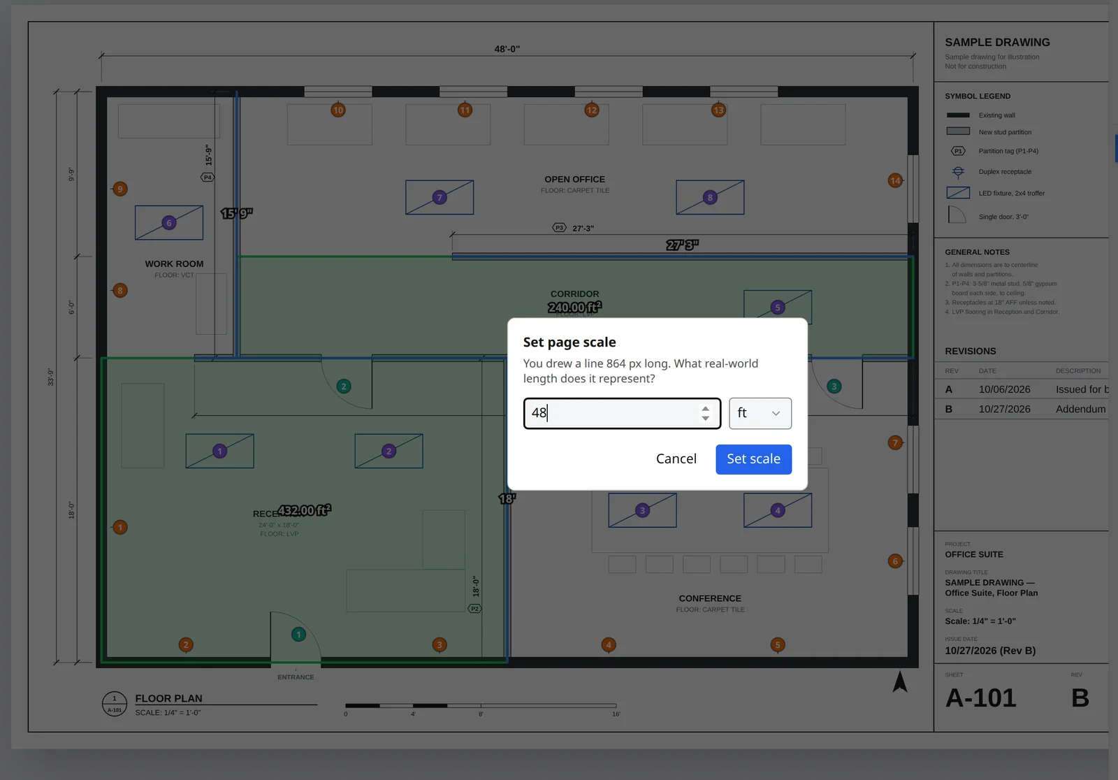
When you measure on a PDF, the file's page size often does not match the original sheet size, so the scale must be calibrated against a known dimension before you take any measurements. Our step-by-step guide on how to scale a PDF drawing accurately covers this in detail.
Step 4: Follow Plans, Sections, Elevations and Schedules Together
No single sheet tells you everything about an item. The skill that separates estimators from people who just measure is tracing one item across the set. Take an interior partition wall as an example:
- Floor plan (for example A-101): find the wall, note its wall type tag, and measure its run in linear feet. Note door tags on the wall.
- Partition types or sections (for example A-301 or A-501): look up the wall type to find the stud size, number of board layers each side, insulation, and whether it runs to the ceiling or to the underside of the deck.
- Reflected ceiling plan: identify ceiling levels, bulkheads and interfaces with partitions. Confirm the actual wall termination height against the partition type, sections, details and specifications. A ceiling height does not necessarily equal the partition height.
- Door schedule: confirm each door's size, type and frame, so openings can be counted and deducted where your method requires it.
- Specifications: confirm the board type, fire or acoustic rating and finish level.
Here is the same chain as a quick reference:
| Where to look | What it tells you about the wall |
|---|---|
| Floor plan | Location, run length, wall type tag, door tags, section or detail callouts |
| Partition types or section | Stud size, board layers, insulation, intended height |
| Reflected ceiling plan | Ceiling levels and bulkheads the wall meets |
| Door schedule | Door sizes, types and frames for each tagged opening |
| Specifications | Board type, ratings and finish level |
Only once you have done this do you know what you are actually measuring. The same chain works for flooring (plan, finish schedule, details at thresholds), ceilings (RCP, sections, details) and openings (plan, elevations, schedules). For the measuring itself on that wall, see our drywall takeoff guide.
Step 5: Identify What Needs to Be Measured for a Takeoff
With the scope understood, decide how each item will be measured:
| Measurement | Typical items |
|---|---|
| Linear feet (LF) | Wall runs, baseboard, trims, curbs, pipe and duct runs, fencing |
| Square feet (sq ft) | Floor and ceiling areas, wall finishes, roofing, slabs |
| Counts (each) | Doors, windows, fixtures, outlets, light fittings, equipment |
| Calculated quantities | Concrete volumes, wall areas from length times height, waste allowances |
Group items by trade and by type before you start, so each one gets its own named condition rather than being mixed into a single total. Decide too how you will handle openings and waste, and apply your waste allowances to the net quantities afterwards rather than measuring them in.
Step 6: Measure Construction Drawings Using PDF Takeoff Software
Once you can read the drawings, measuring from the PDF is the fast part. In SolidTakeoff the workflow is:
- Upload the PDF drawing set and open the sheet you need.
- Calibrate or verify the scale against a written dimension.
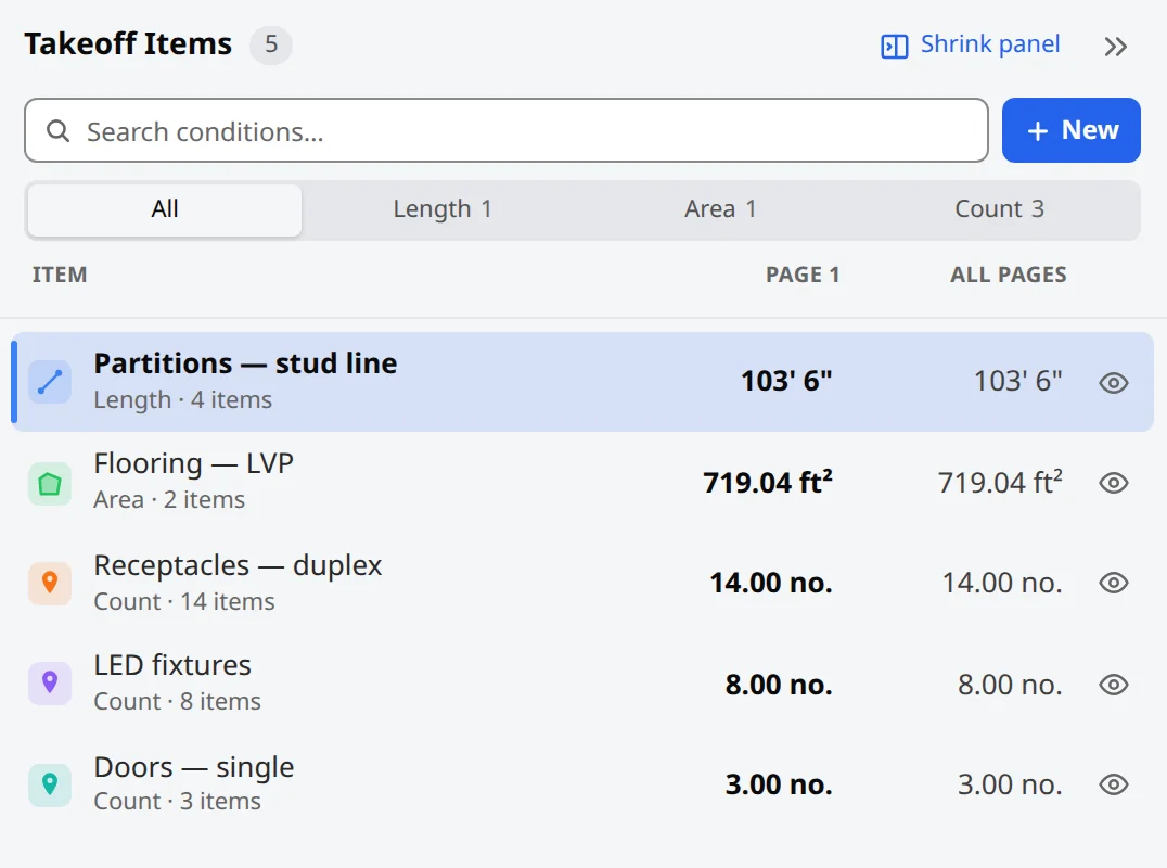
- Create named conditions for each item, such as "Partition Type 1", "Carpet Tile" or "Door Type A".
- Measure lengths, areas and counts directly on the plan. Totals update as you go.
- Export the quantities as a CSV for your pricing spreadsheet, or as an annotated PDF so others can see exactly what was measured.
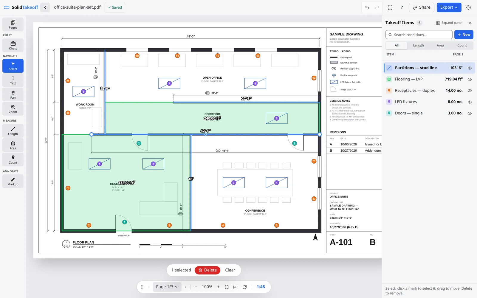
For the complete measuring method, read how to do a construction takeoff.
Common Construction Drawing Reading Mistakes
- Using an outdated revision. Always check the title block and revision table against the latest issue.
- Measuring at the wrong scale. Mixed scales on one sheet and PDFs exported at a different size catch out even experienced estimators.
- Missing detail and section sheets. Trims, upstands and edge conditions often only appear on details.
- Misreading symbols or tags. A wall type tag or finish code that is read wrongly changes every quantity linked to it.
- Ignoring notes and specifications. "Typical" notes and spec sections can add scope that the plans do not show.
- Not checking for NIC or by-others items. Measuring scope that is not in your contract inflates the bid.
Before submitting, run through our construction takeoff checklist to catch these issues.
How to Read Construction Drawings in Australia
The principles are the same in Australia, but a few conventions differ:
- Metric scales. Floor plans are commonly drawn at 1:100, with enlarged plans and sections at 1:50 and details at 1:20, 1:10 or 1:5. Dimensions are usually in millimeters.
- Drawing standards. Australian technical drawing conventions are informed by the AS 1100 series, including its architectural drawing provisions. Individual consultants may use different sheet numbering and presentation conventions, so always follow the project's drawing register and legend.
- Terminology. You will see plasterboard rather than drywall, and quantities may need to match a bill of quantities (BOQ) prepared by a quantity surveyor on larger projects.
- Specifications. Many projects use NATSPEC-based specifications alongside the drawings.
Measure in metric units that match your tender documents, and calibrate the PDF against a millimeter dimension before you take any quantities.
Ready to Measure the Drawings You Have Just Learned to Read?
Open your PDF in SolidTakeoff, verify the scale, measure lengths, areas and counts, and export the quantities for pricing. Start free, no credit card required.
The free plan includes 1 active project and 3 drawing uploads in total. Solo is $12.99 a month, and Team is $49.99 a month for three users, then $16.99 per extra user. Full details are on the pricing page.
SolidTakeoff is a measurement tool. It does not replace reading the specifications, checking design coordination or resolving drawing discrepancies with the design team.
Frequently Asked Questions About Reading Construction Drawings
What is the best way to learn how to read construction drawings? Start with one complete drawing set. Read the cover sheet and drawing index, then follow a single item, such as one wall or one door, from the floor plan through the sections, details, schedules and specifications.
What do the letters and numbers on construction drawing sheets mean? In many US sets the letter is the discipline (A for architectural, S for structural, M, E and P for mechanical, electrical and plumbing) and the first digit is the sheet type (1 for plans, 2 for elevations, 3 for sections, 5 for details, 6 for schedules). Always confirm against the project's drawing index.
Where do I find the scale on a construction drawing? Under each view title, in the title block if the sheet has one scale, and on any graphic scale bar. Use written dimensions wherever they are given.
What is the difference between a plan, an elevation and a section? A plan is a horizontal cut seen from above, an elevation is a face seen straight on, and a section is a vertical cut through the building that shows how it is built up.
Can I do a takeoff directly from PDF drawings? Yes. PDF takeoff software lets you calibrate the scale and measure lengths, areas and counts on screen, then export the quantities. Check the scale against a known dimension on every sheet first.